Showing posts with label Circuits4u. Show all posts

Thursday, November 1, 2012

LM1830 based liquid level indicator circuit


.

LM1830 is a monolithic integrated circuit that can be used in liquid level indicator / control systems. Manufactured by National Semiconductors, the LM1830 can detect the presence or absence of polar fluids . Circuits based on this IC requires minimum number of external components and AC signal is passed through the sensing probe immersed in the fluid. Usage of AC signal for detection prevents electrolysis and this makes the probes long lasting. The IC is capable of driving a LED, high impedance tweeter or a low power relay at its output.
liquid level sensor
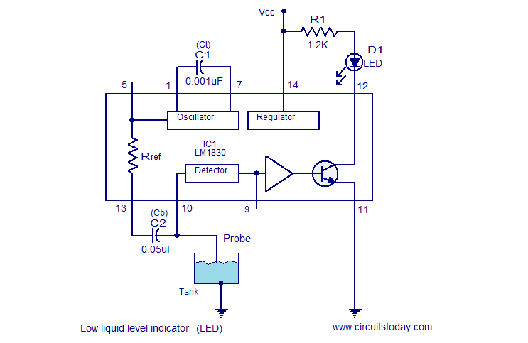
Low liquid level indicator (LED)
The circuit of a low liquid level indicator with LED is shown above. Capacitor Ct sets the frequency of the internal oscillator. With the give value of C1 the frequency will be around 6KHz. Capacitor Cb couples the oscillator output to the probe and it ensures that no DC signal is applied to the probe. The circuit detects the fluid level by comparing the probe to ground resistance with the internal reference resistor Rref.
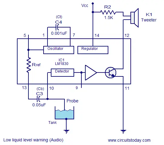
When the probe to ground resistance goes above the Rref the oscillator output is coupled to the base of the internal output transistor making it conducting. The LED connected to the collector (between pin 12 and Vcc) is driven. Since the base of the transistor is driven using the oscillator, actually the transistor is being switched at the oscillator’s output frequency @50% duty cycle. There is no problem in driving the LED using AC signal and this method is very useful when it comes to use a loud speaker as the indicator. Loud speakers can be driven only by using AC signals and a DC signal will not produce any sound out of the speaker. The circuit diagram of a liquid level indicator using loud speaker at its output is shown below. The circuit is similar to the first circuit except that the LED is replaced by a loud speaker and the load current limiting resistor is changed from 1.2K to 1.5K.
low liquid level alarm
Low liquid level warning (audio)

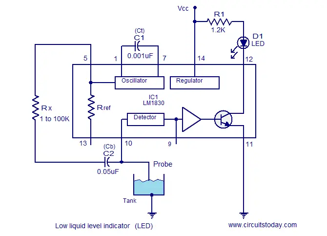
Low liquid level indicator with external reference resistor.

Some time there may be situations when the fluid resistance (probe to ground) do not match with the 13K internal reference resistor. In such cases there is option to avoid the internal reference resistor and an external reference resistor of your choice (Rx in the circuit) can be employed. The oscillators output is directly available at pin 5 and the Rx connects the oscillator output to the probe through the blocking capacitor. The circuit diagram for the above said scheme is shown below.
fluid level indicator
Level indicator using external reference resistor


High liquid level activated switch.

A method for activating a relay when the liquid level exceeds a predetermined level is shown here. DC voltage is required for driving the relay and AC voltage cannot be used here just like what we did in the case of LED and speaker. Pin 9 of the IC can be used to solve this problem. A capacitor connected from this pin to ground will keep the internal output transistor steadily ON whenever the probe resistance goes higher than the reference resistor. External transistor Q1 is connected to the collector of the internal transistor. The load that is the relay is connected at the collector of Q1. When the probe is not touching the water it equal to an open circuit situation and surely the probe resistance will be many M ohms and it is greater than the Rref(13K). The internal transistor will be switched ON and Q1 whose base is connected to the collector of the internal transistor will be in OFF condition keeping the relay inactive. When the reverse scenario occurs (fluid level touches the probe) the internal transistor is switched OFF and this in turn makes the transistor Q1 ON resulting in the activation. The load connected through the relay whether pump, lamp, alarm, solenoid valve or anything is driven. Resistor R3 limits the collector current of the internal transistor while resistor R4 provides protection to the IC from transients.
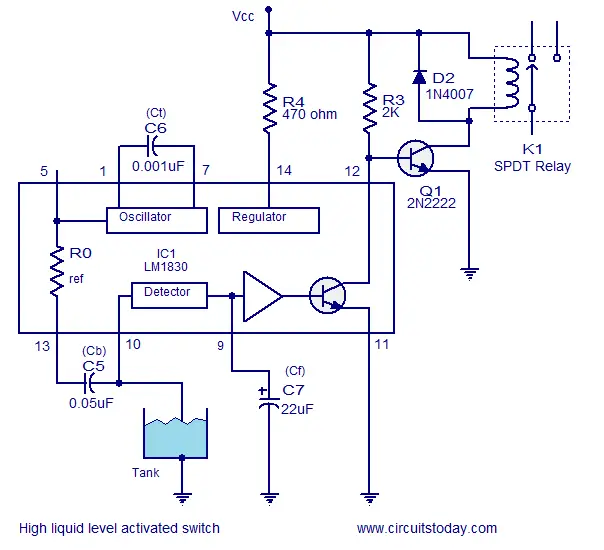
high fluid level activated relay
High liquid level activated switch
Probe: The probe used here can be any metal rod with size and shape of your choice. The tank must be made of metal and it should be properly grounded. For non metal tanks fix a small metal contactor at its bottom level and ground it. The probe must be placed at the level you want to monitor.
Notes.
  • The circuit can be assembled on a Perf board.
  • I used 12V DC for powering the circuit.
  • Maximum supply voltage LM1830 can handle is 28V.
  • The tweeter I used was of a 16 ohm type.
  • The relay I used is a 200 ohm/12V type.
  • Maximum load current Q1 (2N2222) can handle is 800mA.
  • The switching current/voltage ratings of the relay must be according to the load you want to drive using it.
  • It is recommended to mount the IC on a holder.

Saturday, October 27, 2012

Simple DC power delay circuit


Description.
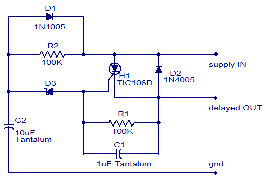
The circuit diagram shown here is of a simple DC power delay circuit that is based on an SCR. This circuit is a very handy one and can be employed in many applications. The working of this circuit is very simple. When the input power is applied the capacitor C2 charges through resistor R2 and when the voltage across the capacitor just exceeds the Zener diode D3’s breakdown voltage, it breaks down and the SCR H1 is triggered and the delayed power will be available at the delayed OUT terminal.
Circuit diagram.
dc power delay circuit
Notes.
  • The circuit must be assembled on a good quality PCB.
  • The Zener diode must be rated half the input supply voltage.
  • The current capacity of the circuit depends on the SCR and here it is 4A.

Friday, October 26, 2012

Burglar Alarm


Burglar Alarm


      The circuit illustrated here is used as an Burglar alarm. LDR is kept at such a place that when thief enters our house then a shadow will fall on the LDR. A small beam of light source is also needed to supply continuous signal to LDR. For best Light source we can use Laser diode which will work for few KMs. For home use Infra Red LED’s will be good and will be tricky to thief and works with same efficiency at night.
      This circuit uses a popular timer I.C which is 555. I.C 555 is connected as comparator with pin 6 connected with positive supply, the output goes high-1 when the trigger pin 2 is at lower than 1/3 level of the supply voltage. Conversely the output goes low-0 when it is above 1/3. So small change in voltage of pin 2 is enough to change the output state of pin 3 from 1 to 0 and 0 to 1. The output has only two states high and low and can not remain in any intermediate stage. It is power by 9V battery for portable use. The circuit is economic in power consumption. Pin 4,6& 8 is connected to the positive supply and pin 1 is grounded.
      To detect the present robber we have used LDR and a source of light.
LDR is a special type of resistance whose value depends on the brightness of the light which is falling on it. It has a resistance of about 1 megaohms when in total darkness,but a resistance of only about 2-5 k ohms when brightly illuminated. It responds to a large part of the light spectrum.
      The source of light and LDR is so adjusted with a reflector that light will directly fall on the LDR but when robber enters inside then it will block the beam of light and LDR will be under darkness.
      We have made a potential divider circuit with LDR and 100 K variable resistance connected in series. Voltage is directly proportional to conductance so more voltage we will get by this divider when LDR is getting light and low voltage in darkness. Sensitiveness can be adjusted by variable resistance. Divided voltage is given to pin 2nd of 555. As soon as LDR gets dark the voltage of the pin 2 drops 1/3 of the supply voltage and pin 3 gets high and Buzzer Beeps.
For Demo we have used simple LED for LED1 may be Red or White Color

                        Burglar Alarm Circuit Diagram
LED = Light Emitting Diode
LDR = Light Dependent Resistance
IC = Integrated Circuit
Components:-
1) 9V battery with snap
2)LDR
3)Variable resistance 100K ohms
4)Resistance 470 ohms
5)LED
6)IC 555
7)Switch

Heat Sensor


Heat Sensor


Here is a simple circuit which can be used as a heat sensor. In the following circuit diagram thermistor and 100 Ohms resistance is connected in series and makes a potential devider circuit . If thermistor is of N.T.C (Negative temperature Coefficient ) type then after heating the thermistor its resistance decreases so more current flows through the thermistor and 100 Ohms resistance and we get more voltage at junction of thermistor and resistance. Suppose after heating 110 ohms thermistor its resistance value become 90 Ohms.then according to potential devider circuit the voltage across one resistor equals the ratio of that resistor’s value and the sum of resistances times the voltage across the series combination. This concept is so pervasive it has a name: voltage divider. The input-output relationship for this system, found in this particular case by voltage divider, takes the form of a ratio of the output voltage to the input voltage.
    This output voltage is applied to a NPN transistor through a resistance. Emitter voltage is maintain at 4.7 volt with a help of Zener diode.
This voltage we will use as compare voltage. Transistor conducts when base voltage is greater than emitter voltage. Transistor conducts as it gets more than 4.7 base Voltage and circuit is completed through buzzer and it gives Sound.
Heat Sensor Circuit Diagram
(courtsey: http://circuiteasy.com )